
Palfinger Loader Cranes
Notice: Undefined variable: out in /mnt/wordpress_data/fo.kj/wp-content/themes/twentyseventeen-child/template_palfinger.php on line 281
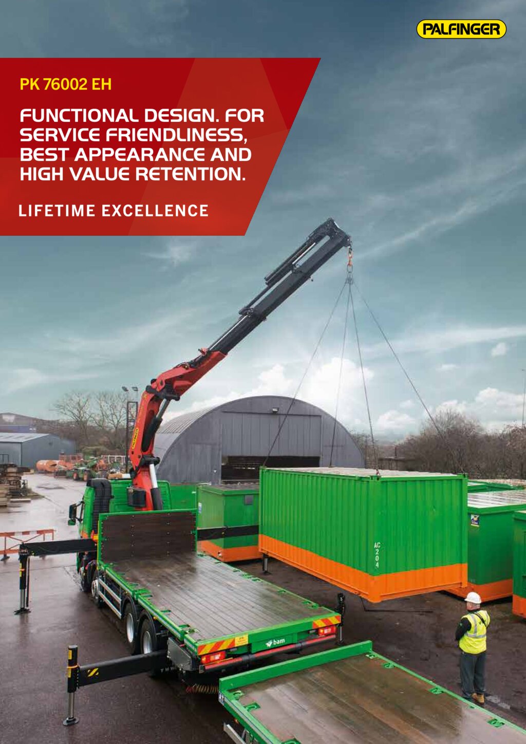
PK 76002 EH High Performance
Functional Design. For service friendliness, best appearance and high value retention.
- Additional applications due to Power Link Plus
- Maximum utilisation of the working range due to HPSC
- Practical and attractive due to Functional Design
- More lifting power due to E-HPLS
Brochures
PK 76002 EH
| Max. lifting moment | 71.6 |
| Max. lifting capacity | 23000 |
| Max. hydraulic outreach | 20.4 |
| Max. manual outreach | 25.1 |
| Max. outreach (with fly jip) | 30.5 |
| Slewing angle | ∞ |
| Slewing torque with 1 gear | 4.5 |
| Slewing torque with 2 gears | 7.0 |
| Stabilizer spread (std) | 8.6 m |
| Fitting space required (std) | 1.71 |
| Width folded | 2.55 |
| Max. operating pressure | 350 |
| Pump capacity | 80 - 100 l/min |
| Dead weight (std.) | 5910 |
Cranes shown in the leaflet are partially optional equipped and do not always correspond to the standard version.
Country-specific regulations must be observed. Dimensions may vary. Subject to technical changes, errors and translation mistakes.
Country-specific regulations must be observed. Dimensions may vary. Subject to technical changes, errors and translation mistakes.
Lifting moment | Outreach | Slewing angle | Slewing torque (mt) | Pressure | Pump capacity (l/min) | Crane Weight | Crane Height | Crane Width | Installation Width | Max stroke lenght | Max lifting capacity | Load vertical | |
|---|---|---|---|---|---|---|---|---|---|---|---|---|---|
| A | 69.1 mt | 7.6 m | ∞ | 4.5 / 7.0 | 35.0 Mpa | 80-100 | 5908 kg | 2455 mm | 2550 mm | 1555 mm | 7434.45 mm | 23000 kg | 9500 kg |
| B | 68.2 mt | 9.5 m | ∞ | 4.5 / 7.0 | 35.0 Mpa | 80-100 | 6246 kg | 2455 mm | 2550 mm | 1555 mm | 9366.45 mm | 23000 kg | 7400 kg |
| C | 67.2 mt | 11.5 m | ∞ | 4.5 / 7.0 | 35.0 Mpa | 80-100 | 6580 kg | 2455 mm | 2550 mm | 1555 mm | 11368.45 mm | 23000 kg | 5800 kg |
| D | 66.3 mt | 13.7 m | ∞ | 7.0 | 35.0 Mpa | 80-100 | 7040 kg | 2455 mm | 2550 mm | 1555 mm | 13578.45 mm | 22000 kg | 4600 kg |
| E | 65.6 mt | 15.9 m | ∞ | 7.0 | 35.0 Mpa | 80-100 | 7310 kg | 2455 mm | 2550 mm | 1555 mm | 15774.45 mm | 21500 kg | 3700 kg |
| F | 65.0 mt | 18.1 m | ∞ | 7.0 | 35.0 Mpa | 80-100 | 7730 kg | 2455 mm | 2550 mm | 1685 mm | 17963.45 mm | 21000 kg | 3100 kg |
| G | 64.5 mt | 20.4 m | ∞ | 7.0 | 35.0 Mpa | 80-100 | 7730 kg | 2455 mm | 2550 mm | 1685 mm | 20266.45 mm | 20500 kg | 2550 kg |
The outreaches stated are with a boom angle of 20° and are therefore not the maximum. When using mechanical boom extensions, the loads shown on the charts need to be reduced by the weight of these extensions.